Developing scalable traction inverters for compact electromobility solutions
The broad spectrum of electromobility, ranging from the conveyance of individuals to the transportation of commercial goods, requires efficient, reliable and affordable forms of drivetrains.
By Philipp Mai, Vice President Engineering EMEA – Automotive & Transportation, Arrow Electronics
The term ‘electromobility’ is commonly associated with the electrification of automobiles. However, the concept of e-mobility extends far beyond this market to cover various contemporary forms of mobility. Examples include electrically-powered scooters, motorbikes and small utility vehicles. While e-scooters contribute to local emissions reductions, mainly in urban areas, e-motorbikes and electric small utility vehicles are increasingly being used as sustainable alternatives for wider leisure, transport and logistics purposes.
This broad spectrum of electromobility, ranging from the conveyance of individuals to the transportation of commercial goods, requires efficient, reliable and affordable forms of drivetrains. The traction inverter is a prime example. This key component transforms the direct current (DC) supplied by a battery into alternating current (AC) that can be used by the motor, as well as adjusting speed and engine torque to meet user requirements.

Fig 1. Example of cost breakdown
Power variations
While battery-powered automobiles require high-voltage
battery packs (400 V/800 V) to ensure sufficient performance and range,
low-voltage batteries in the range of 36 V to 96 V have become standard for
other forms of e-mobility systems. These diverse power requirements demand
different technological solutions from the corresponding traction inverters.
In each case, the traction inverters must be designed to
conform to the relevant technical framework conditions and the specification
profiles. During development, particular emphasis is placed on:
• Compact
construction
• High
efficiency
• Cost-effectiveness
• Robustness
and reliability
• Functional safety
To meet these requirements, it is advisable to start with a basic concept that is scalable to the required power (typically 3 to 5 kW) and voltage range (36 to 96 V). Particular attention should be paid to the circuitry design, because it enables adaptation to the varying use profiles and determines the cost of the inverter. (Fig 1.)
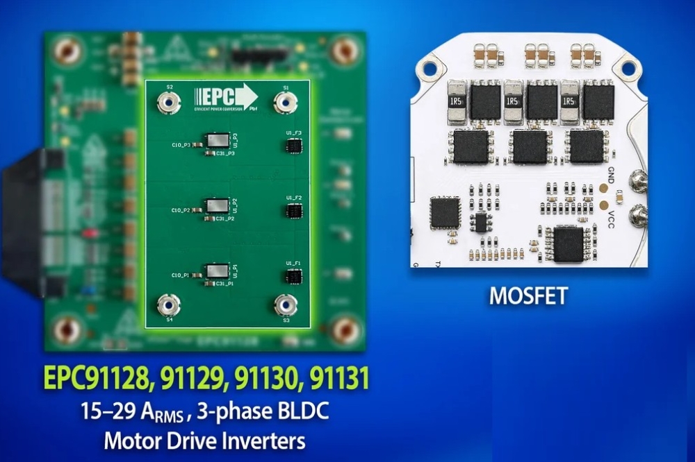
MOSFETs and power modules
The use of MOSFETs in SMD housings is one tried and tested
concept for the design of final circuitry in low-voltage traction inverters.
This approach allows the heat generated to be transferred via the circuit board
to a cooling element or the housing for dissipation. Thermal vias with
aluminium base PCBs have emerged as the most cost-effective solution for this
application. (Fig 2.)
However, a disadvantage of this concept is the excessive
heating of the PCB. This can make it impossible to position the necessary
filter capacitors directly in connection with the PCB, as the increased heat
input would significantly reduce their service life. As a result, the
corresponding designs are frequently more complex and less compact.

Fig 2. SMD Concept
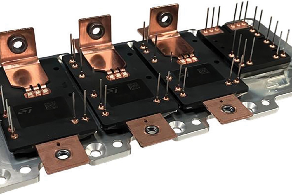
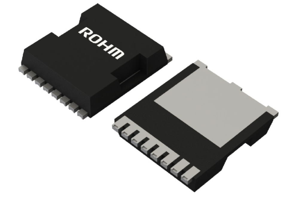
TSC (top-side cooled) MOSFETs have subsequently become the solution of choice in high-power applications. (Fig 3.)
This method offers the distinct advantage that MOSFETs can be directly connected to a cooling element, providing effective discharge of heat. In addition, a more cost-effective PCB can be employed. However, increasing performance demands mean that parallel connection of the MOSFETs becomes essential, which in turn results in additional complexity of designs (thermal management, layout, eMV) and makes compact construction more difficult.
Although both these methods are scalable, their respective disadvantages limit their use within contemporary low-voltage traction inverters, especially when trying to meet challenging load and performance requirements. A viable alternative can be found in the type of power modules used in e-vehicles.
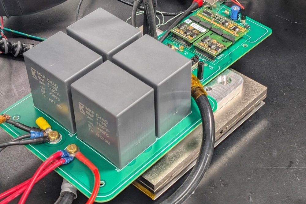
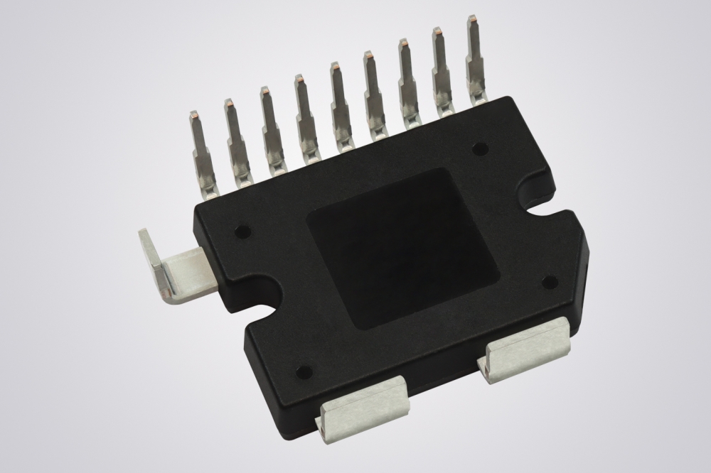
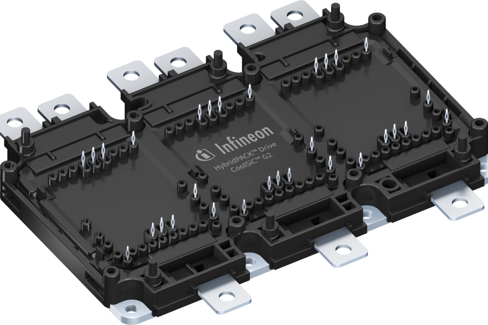
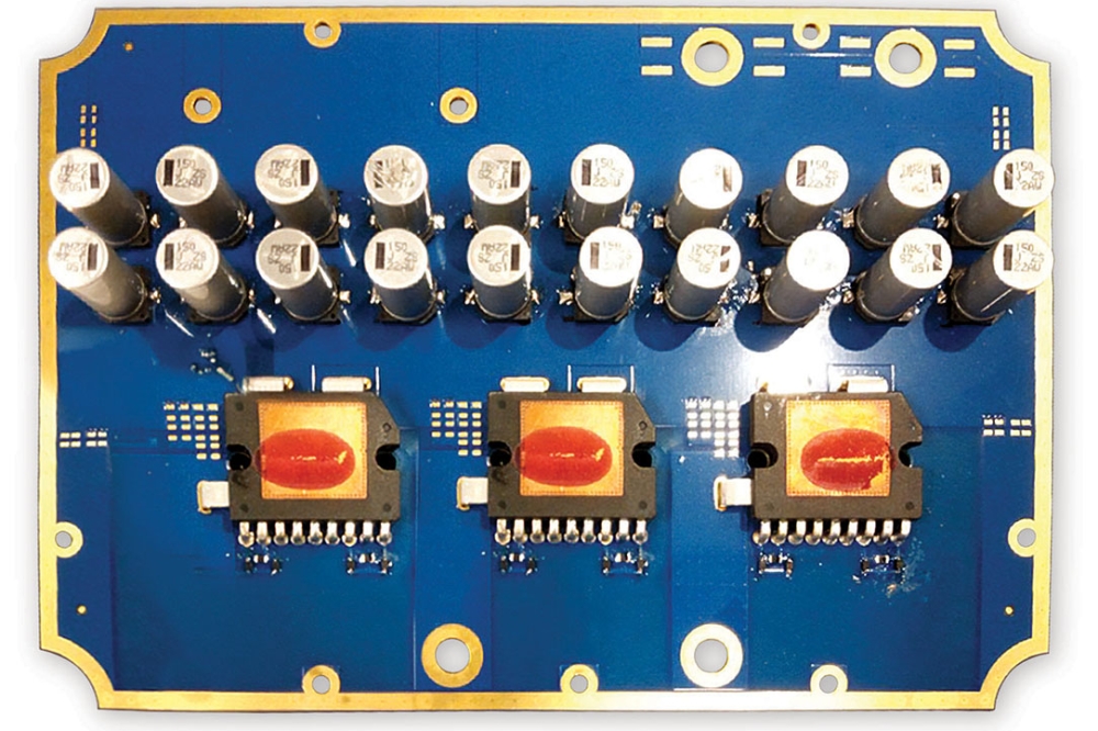
Power modules offer several advantages in the context of contemporary low-voltage traction inverters. Features such as component integration and efficient thermal management enable a compact inverter design and reduce development costs. In addition, power modules are more reliable because they have lower failure rates than more discrete solutions. Their design also makes scalability easier, allowing developers to adapt circuitry more rapidly and cheaply to the various power and voltage classes. An example of such a module is illustrated in Fig 4.
Making good contacts
In addition to the design for the final circuitry, the
contacts required for high currents represent a challenge for developers. In
the past, simple screw contacts and ring cable lugs were often employed.
Although cost-effective, this method no longer conforms to current reliability
and safety requirements.
A modern contact system must exhibit minimal contact resistance and offset tolerances and provide a reliable contact despite the extensive shock, vibration and thermal cycles to which the system will be exposed. The contact system must therefore be based on a locking design.
The SW1 COEUR by Molex is one such example. (Fig 5.)
Despite its high current-carrying capacity, this contact
system has a compact design, allowing it to be readily installed in the field
or in workshops. There are three different contact system sizes (6.00, 8.00 and
11.00 mm), facilitating scalability and cost-effective adaptation to
various circuitry designs requiring currents of up to 300 A.
A matter of control
Using the correct control card is essential in ensuring the
scalability of a low-voltage traction inverter - and the microcontroller plays
a key role. Solutions are widely available for providing sufficient power to
process the complex algorithms that control the motor (such as FOC -
field-oriented control) and suitable peripherals (e.g. precise PWM generation
or ADC). However, they are not always cost-effective and offer only limited
options regarding functional safety. . This is a concern because the functional
safety of the microcontroller and the system as a whole is becoming
increasingly important in gaining access to international markets for compact
e-mobility solutions.

Fig 3. TSC Concept

Fig 4. Vishay module

Fig 5. The SW1 COEUR
When choosing a suitable microcontroller, hardware features
are no longer the most crucial factor. Increasingly, it is the software that
determines the complexity and costs of traction inverter development. For
example, the S32K3 family by NXP offers a microcontroller platform suitable for
low-voltage traction. These units come with certified software packages for use
in the field, such as Real-Time (RTD) and Safety Peripheral Drivers (SPD),
ASIL D, an AMMCL (Advanced Math and Motor Control Library), SAF (Safety
Software Framework), and a Structural Core Self-Test (SCST) Library. This
significantly reduces the necessary design input.
Isolation aspects
Galvanic isolation is a further consideration in designing
and scaling compact systems for e-mobility. In circumstances where low-voltage
traction inverters are exposed to moisture, dust and soiling, the isolated
driver circuit design not only provides efficient control of a MOSFET but also
supports the reliability and galvanic isolation of the system as a whole.
For high-voltage traction inverters, special gate drivers
are used. These are considered oversized for use with systems operating at
voltages below 96 V. One example of a potentially suitable gate driver is the
Si8285CD-AS by Skyworks. In addition to sufficient capacity and isolation, it
offers suitable integrated safety features (UVLO, DESAT), together with a
dedicated pin for automatic feature activation.

Vishay control board
Achieving a complete, scalable design
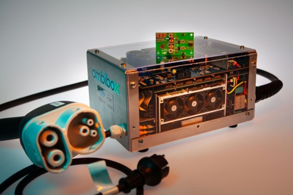
The Arrow reference design, developed by Arrow Electronics
in collaboration with its partner Vishay, represents a complete, scalable
low-voltage traction inverter for compact e-mobility solutions. The control
board and circuitry are strictly separated to provide for modularity.
The emphasis is on a scalable, final circuitry design based on an innovative, top-side cooled power module by Vishay. This module design allows for flexible and effective adaptation to various performance classes from 3 kW to 15 kW and voltage classes up to 96 V – all within a single form factor. To optimise the form factor, Vishay SMD hybrid capacitors have been attached to the circuitry system and directly integrated into the cooling concept of the power modules. This innovative combination of functionality and flexibility opens up a wide range of possible applications, setting new standards in the design of final circuitry for use in compact e-mobility solutions.
The control board has been developed with a clear focus on reliability and safety. The isolation provided (1 Kvdc) ensures the system can be flexibly used across various voltage classes, making it versatile and robust. Various aspects relating to functional safety were considered during development, including the comprehensive use of safety PMICs from the FS23 family by NXP. These are characterised by a wealth of features that provide for a wide range of diagnostic operations and thus ensure system integrity. Moreover, the gate drivers are monitored by a diagnostic output that ensures early detection of malfunctions. The phase voltage and current of the final circuitry design are measured and monitored by isolated amplifiers from the Si89xx series by Skyworks.
This combination of integrated safety features and reliable
design concepts provides the highest level of performance. It also complies
with the most stringent requirements for safety-critical low-voltage traction
inverters for use in e-mobility applications, from electrically-powered
scooters to commercial vehicles.